This article was published in Smart Soldier 67, February 2022.
Introduction
A map provides a graphical representation of a part or the whole of the Earth’s surface shown on a planar (2-D) surface. It depicts both man-made and natural features, usually with an applied geographic coordinate system, and usually with a key or legend. Maps are used to show where something is relative to all the other things around it – and the relationships between those entities. But how do you tell others where something is? It is easy to identify a specific location on a map; the problem arises when you have to tell someone else the location, especially when they are not standing next to you and looking at the same map. How do you relate this information to another person or group of people? The answer is to use a coordinate system.
The Australian Geospatial-Intelligence Organisation (AGO) is responsible for Defence’s topographic mapping. Within Australia, AGO’s focus is on mapping ADF training areas – referred to as Australian Specials (AUSPECs). These are produced using the North Atlantic Treaty Organization’s (NATO) coordinate standard – the Military Grid Reference System (MGRS). Civilian mapping agencies tend to use the Universal Transverse Mercator (UTM) reference system instead.
Why coordinates are important
Coordinates are an essential element for mapping, both in identifying a location and for the purposes of navigating. Coordinates are used to give an accurate position for a point on the Earth’s surface. If coordinates are not obtained correctly from a map, or if the wrong coordinate system is used, then erroneous location information will be provided. A simple error such as this can have devastating and deadly consequences in a military context.
An example of this going horribly wrong in a military context occurred when a soldier directing a bomb strike gave incorrect coordinates, which resulted in a friendly airstrike on a HQ of allies that caused multiple deaths and injuries.
The challenge that soldiers face when using maps provided by external organisations is that these maps are produced using UTM grids and coordinates. An example of this is provided in Figure 1.
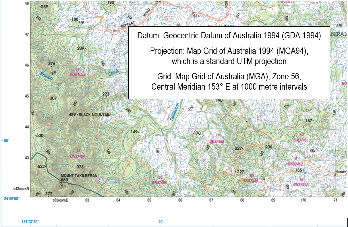
Figure 1. QTopo State mapping grid example and product note [1]
Soldiers have become reliant on MGRS and may be unaccustomed to seeing UTM coordinates. This could cause confusion and frustration in what may be a stressful and time-poor environment, resulting in errors such as the previously provided example. Knowing how to plot MGRS coordinates from UTM coordinates is becoming more and more necessary within the military, particularly when operating in areas that have not been mapped for military purposes.
Currently the AGO Map Request Tool provides State mapping that utilises the UTM reference system. The map displays all grid labels in UTM coordinates (metres) and the production note (as shown in Figure 1) informs users of the Grid Zone (shown as the MGA Zone in this example).
MGRS coordinates
MGRS is the coordinate standard utilised by NATO militaries for locating points on the earth’s surface. MGRS is derived from a UTM grid system and is an alternative way of representing UTM coordinates [2].
The example map shown in Figure 2 has grid lines spaced every 1000 metres. The grid is labelled with UTM coordinate values. The vertical grid lines determine East-West position and the horizontal grid lines determine North-South position. Mapping specials will have an MGRS reference note with information as per Figure 2.
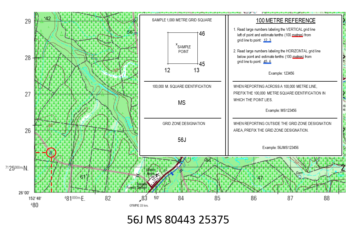
Figure 2. Example MGRS map and MGRS reference
With MGRS, the world is divided into 60 longitudinal bands numbered 1 through 60, with each longitudinal band having a width of 6 degrees, and 20 latitude bands lettered C to X (omitting I and O to avoid confusion with numbers), with each latitudinal band normally having a height of 8 degrees [3]. The intersection of these bands defines the grid zone designation (GZD). In the example shown in Figure 2, the GZD is 56J.
The GZD is followed by the 100,000-metre square identification (or, in short, the ‘100k Ident’). The 100k Ident divides each GZD into squares with a width and height of 100 kilometres. The 100k Ident is a letter-pair that consists of a column letter (A–Z, omitting I and O) followed by a row letter (A–V, omitting I and O). In the example shown in Figure 2, the 100k Ident is MS.
Eastings, 80443, represents a measurement of an East-West position, within the 100k Ident, in metres. Using a map with a 1000 m grid, the first two digits come from the large print on the label for the grid line to the west of the position. The last three digits are the distance in metres measured from the western grid line.
Northings, 25375, represents a measurement of North-South position, within the 100k Ident, in metres. Using a map with a 1000 m grid, the first two digits come from the large print on the label for the grid line to the south of the position. The last three digits are the distance in metres measured from the southern grid line.
These elements are then combined to give a full MGRS coordinate as per the example shown in Figure 2 - 56J MS 80443 25375.
MGRS coordinates can be shortened. In some circumstances, users may want to reduce the coordinate of a position to the appropriate precision level depending on the scale and nature of the task. In this situation coordinates are shortened and not rounded and refer to the bottom-left corner of the designated square, examples of this are:
| 56J MS 56J MS 8 2 56J MS 80 25 56J MS 804 253 56J MS 8044 2537 56J MS 80443 25375 |
(Identifying a 100 kilometre square) (Identifying a 10 kilometre square) (Identifying a 1 kilometre square) (Identifying a 100 metre square) (Identifying a 10 metre square) (Identifying a 1 metre square) |
UTM coordinates
A UTM coordinate comprises a zone number, a hemisphere (N/S), an easting and a northing. Eastings are referenced from the central meridian of each zone, and northings from the equator – both in metres.
UTM zones are divided in the same way MGRS zones are divided, although there is no letter designation after the zone number. Instead this letter indicator is replaced with an ‘N’ or ‘S’ depending on which hemisphere the map is within.
Unlike MGRS, UTM has no 100k Idents as they are substituted with the coordinate numbers at the beginning of the eastings and northings. Different to MGRS having up to 10 numbers (5 for eastings and 5 for nothings), UTM has 13 numbers (6 for the eastings and 7 for the northings).
As with the MGRS example, the two UTM grid lines are 1000 metres apart. The horizontal grid lines are labelled in a similar manner, also being 1000 metres apart.
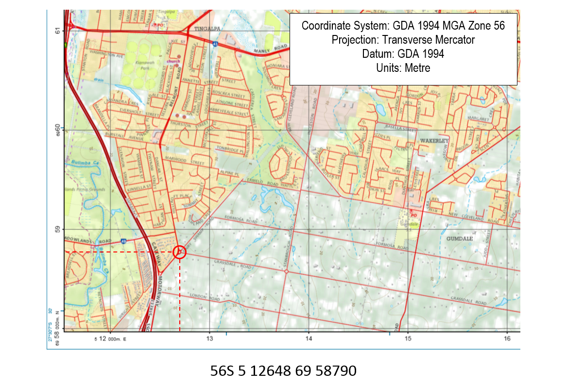
Figure 3. Example QTopo UTM coordinates map
In the example shown in Figure 3, the GZD is 56S, with the ‘S’ representing the southern hemisphere. Unlike MGRS, UTM eastings and northings include the small numbers shown in the bottom left corner of the map. The easting is given in metres, being 5 12648. The northing is also given in metres, being 69 58790.
Obtaining MGRS coordinates from UTM mapping
Seek advice from the Geospatial Intelligence (GEOINT) personnel in your unit or base, or if on operations the GEOINT personnel force assigned. They can provide advice on the GZD and 100k Idents for the mapping you will be using, and how to extract a grid reference from UTM mapping.
If you don’t have access to GEOINT personnel you can use GeoViewer 2 before an exercise to understand the MGRS components in your area. GeoViewer 2 software is available on the DPN using either the Chrome or Edge browsers.[4].
Click on the ‘lat and long’ display cell at the bottom right of the screen (next to a small scale bar), select MGRS, and tick the ‘MGRS Grid’ box in the ‘Overlays’ menu option. The map will display the GZD and 100k Idents. If you can’t see them then you are likely zoomed in too far. The location of the cursor will also provide MGRS coordinates for that location [5].
If you would like instructions for how to manually define MGRS coordinates from a UTM map then send an email to army.lessons@defence.gov.au. It is a complex process.
Conclusion
Currently all training areas within Australia are covered by AGO’s AUSPEC mapping which provides the NATO standard MGRS grids that military personnel are accustomed to. State mapping, produced with UTM grids, is provided for areas outside of Defence training areas.
It is important for all ADF members to understand the UTM system, when using State mapping, to mitigate any potential issues that may arise from incorrectly navigating with such mapping. It is also important when using a GPS receiver to understand what coordinates are being displayed on your device in order to prevent any interoperability issues which is particularly important whilst working with other government or civilian agencies.






There is no individual author, so please reference the 'Army Knowledge Centre' as an organisation. Hope that helps!
The Cove Team
Regards,
The Cove Team