Introduction
Engineers are responsible for the emplacement and integration of Tactical Obstacles. Tactical Obstacles are authorised and sited at the Bde level and therefore undertaken by the Brigade in defence. This article provides instructions analysis based on lessons learnt and procedures at the tactical and technical level to enable the employment of Tactical Obstacles on Exercises and Operations. This article should be read in conjunction with doctrine.
The Brigade in the Defence
The Combat Brigade occupies the defence to deny decisive terrain or enable activities by flanking formations. In the defence the Brigade seeks to Destroy or Degrade the enemy while preserving its own combat power to enable the resumption offensive operations.
In terms of killing the enemy, the Defensive position must have an Engagement Area sited on the enemy’s likely avenue of approach to enable engagement by a hierarchy of Weapon Systems that is orchestrated and controlled. Understanding the role of the weapon systems and when they can engage is essential for the effective integration of Obstacles.
The primary means of destroying the enemy by the defender is Artillery. Artillery enables the destruction or disruption of the enemy at ranges exceeding the direct fire capability of the attacker. It is efficient and enables the defender to preserve combat power.
Direct fire weapons are subsequently employed to kill the enemy in the close fight. Primarily commencing with Tank main gun, then transitioning to direct fire support weapons such as Javelin, Heavy Machine Gun and Automatic Grenade Launchers. These weapon systems target High Value Targets and attrit the enemy and degrade combat power with higher precision than artillery.
Finally, small arms and short range support weapons (84mm MDFSW and MAG 58) may engage IOT protect DFSW systems and retain ground for Tank/IFV battle positions.
The destruction of the enemy by Artillery and direct fire weapons (tank main gun) engagements is enabled by the tactical obstacle plan. Tactical obstacles generally will not support small arms engagements, these are supported by protective obstacles on and through the position.
Planning
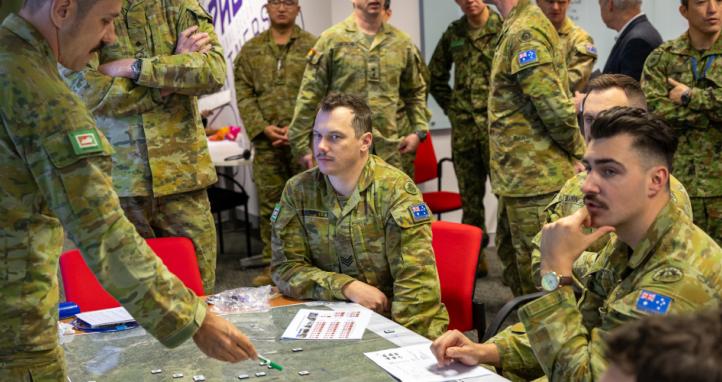
Tactical Obstacles support the Brigade design for battle in the Engagement Area. They shape enemy manoeuvre into areas where they can be killed or force deployment of assets at sub-optimal times and locations. They disrupt the enemy’s Scheme of Manoeuvre and tempo. Accordingly planning for integration of Tactical Obstacles must be conducted as a combined arms team.
The intent and overarching design rests with Commander’s Tac. The Bde Comd supported by CO Artillery and CO Engineers site the Defensive Position and commence Engagement Area development. The Bde commander is responsible for the tactics and design for battle of the Brigade. CO Artillery determines where Artillery can do a majority of the destruction and CO Engineers develops an obstacle plan to shape the enemy into terrain where they can be killed.
Division HQs will have already assigned the Obstacle Zone, this control measure provides the authority for the brigade to emplace obstacles in a designated area. CO Engineers sites the obstacle Belts and assigns their intent in conjunction with the Bde Commanders design for battle and CO Artillery’s Brigade fire plan.
The tactical intent, brigade fire plan and obstacle intent is then passed to the Plans node. Plans staff develop the control measures, assign troops to task and plan the occupation of the Defensive Position. OPSO Engineers ‘Chainsaw’ in conjunction with the BM and Artillery planners further develop the Engagement area plan. OPSO Engineers resources obstacle groups to be emplaced within the Belts provided by CO Engineers and develops the MS Overlay. Engineer assets are assigned to tasks and the Engineer S4 and Bde DQ plan the movement of Class IV from the Brigade Support Group (BSG) to the Engineer A2 echelon.
Execution
To achieve MS effects in support of the Brigade in the Defence, the CER forms a Task Group. This centralises engineers to generate mass and enables effective tasking against priority of effort.
Engineers will achieve two main tasks during this phase. The two primary tasks are the development and integration of Tactical Obstacles and the conduct of survivability works in support of the Battle Groups.
An important distinction must be made at this point and communicated across Headquarters. In terms of survivability works, engineers will conduct expedient excavation of fighting positions and Armoured Fighting Vehicle (AFV) scrapes. Engineers do not have the capacity to concurrently develop tactical obstacles and develop full survivability positions and priority must be apportioned to tactical obstacles in support of the Bde design for battle.
Revetment of fighting pits or trenches and the development of protective obstacles is the responsibility of the BGs in the MDP– it is an all-corps task. Small engineer elements may be assigned to provide subject matter advice or complete complex survivability task such as dug in Command Posts.
Engineers OCs receive the obstacle Belt control measures and resources allocated from the MS Overlay developed by the S35 and OPSO. Post reconnaissance Engineer OCs will develop Obstacle Group control measures and assign CE Tps to emplace. Obstacle Group is a control measure that identifies the specific location of obstacles that when combined achieve the directed effect of the Belt. An example is a FIX Belt maybe be achieved with the following Obstacle Groups: 200m of ATD reinforced with tetrahedrons, three mine panels and a complex wire obstacle. These groups will be arrayed to achieve a FIX effect.
Through all stages of execution Artillery, Engineers and manoeuvre must remain synchronised to ensure that effort is not wasted and that an obstacle doesn’t inadvertently shape the enemy away from a TRP or deny a planned withdrawal route for a friendly element. This is achieved by combining the Bde Defence overlay, MS overlay and OS overlay.
Engineer OCs will provide a consolidated SITREP covering obstacle status and specific locations to inform development of the MS overlay and ensure that obstacles are considered in the manoeuvre plan. Once emplaced an obstacle is Neutral, it will shape both friendly and enemy manoeuvre.
Lanes must be planned and sited through obstacles to ensure the Screening/Covering Force and Standing patrols can retrograde in accordance with the Bde scheme of manoeuvre. Lanes must be marked on the MS and manoeuvre overlays and OS should be integrated to support retrograde of forward elements.
Engineer OCs must resource and task a CE Tp to close lanes through employment of situational obstacles. This action must be rehearsed by day and night to ensure it is executed successfully. Rehearsals should include the triggers to emplace the situation obstacles (i.e. last vehicle through) and a guided walk through by lead vehicles or commanders of the withdrawing force. Closing a lane is a CE Troop task. The assigned force must be capable of providing guides to ensure friendly vehicles do not drive into the obstacle and closing of the lane through situational obstacles.
Security is paramount to ensuring Engineers can emplace obstacles. Security should be layered to provide engineers the ability to work with minimal disruption and to deny enemy Reconnaissance. The Brigade Screening/covering force provides security to the front of the engagement area, while BGs may provide patrols on the flanks. The CE Tp is responsible for local security during obstacle emplacement. In order to maximise engineer output however, consideration should be given to assigning an infantry Section to assist in local security.
There is a high risk of fratricide during obstacle emplacement. Clear control measures must exist controlling actions in the Main Defensive Position and Engagement Area. Battle Groups may control their respective defensive positions, however Brigade controls engagements and movements in the Engagement Area. Battle Groups may be tasked to secure the peripheries of the Engagement area through patrols, however the Engineers must be given freedom of action within the EA.
Fratricide can also be mitigated by submitting obstacle emplacement plans 24 hours in advance, enabling Brigade to cross reference Battle Group patrol plans and de-conflict. Additionally, staffing permitting, Liaison Officers can be attached to Battle Group Head Quarters to advise on Engineer movement in the Engagement Area.
Obstacle Effects
Tactical obstacles achieve four effects. The effect of obstacles should be understood by both Engineers and manoeuvre commanders to ensure the most optimal effect is chosen for the ground and to enable the Brigade Scheme of manoeuvre. Obstacle effects are assigned by CO Engineers using the Belt control measure.
Disrupt. Disrupt obstacles enable penetration along a portion of the enemy’s avenue of approach. Disrupt obstacles force the enemy to change formation while advancing and cause the separation of echelons enabling their piecemeal destruction. Low resource requirement.
Fix. A fix obstacle slows tempo of the advancing force. It forces the commitment of breaching assets and holds or slows the enemy on a piece of ground increasing the ability of offensive support and direct fire weapon systems to destroy them. Medium resource requirement.
Turn. A turn forces the enemy to change direction. This is the primary shaping effect the forces the enemy into a piece of terrain where they can be targeted. Fix obstacles present a hard shoulder that is not economical or feasible to Breach. High resource requirement.
Block. A block obstacle denies an avenue of approach to the enemy. Committing to a breach would be too costly and tactically unsound. Very high resource requirement.
Obstacle effects based on their resource requirements and shaping of the enemy’s scheme of manoeuvre should be sequenced and coherent. They should tell a story about how the Brigade intends to destroy the enemy.
An example of a coherent obstacle plan is as follows: A DISRUPT Belt on the forward edge of Engagement Area disrupts the enemy’s formation causing a reduction in tempo, the separation of echelons and targeting by OS. As the enemy advances they encounter a TURN Belt that forces them away from a concealed avenue of approach and into terrain optimal for engagement. Once turned into the engagement area they encounter a FIX obstacle causing the commitment of MS assets to Breach, reducing tempo, and forcing manoeuvre elements to advance through lanes and occupy an FUP prior to advancing. At this point they are engaged by superimposed offensive support and direct fire weapons systems. Finally, the enemy, heavily attrited encounters a BLOCK Belt. This halts momentum, forces a deliberate breach with diminished MS assets and ultimately sees the culmination of the enemy’s assault.
Obstacle Design
Obstacle design should be informed by the directed obstacle intent and the enemy’s capabilities (platforms and engineer assets). The obstacle must be dense or complex enough to hinder mobility and should aim to consume the maximum amount of Enemy MS resources or overmatch their capability.
The following considerations should be applied to obstacle types:
Tactical Minefields: the variables with an anti-tank minefields are frontage, density and depth.
Frontage is the portion of the Avenue of Approach covered by the minefield. This is not a continuous panel, but the cumulative frontage of panels within the minefield. Density is also determined by the directed effect and determines the probability of a strike.
The depth of a minefield should be determined on the enemy’s breaching capability. It should aim to commit the maximum number of assets to reduce. Depth forces assets to be committed enabling them to be targeted. An example is the GSL-130 Tracked ABV. It is equipped with three GBP-127 MICLICs each capable of reducing 100m. If a minefield is 400m deep, this will require two GSL-130s to be deployed, increasing density of asset and probability of successful engagement and degradation of the Enemy’s MS capability.
Marking of minefields is mandated under the Ottawa Treaty and Protocol II agreements. Tactical minefields are to have a perimeter fence and mine warning signs placed at 10 -50m intervals. While this gives clear indication of the presence of a minefield it also provides an opportunity for deception. The primary mandated requirement of the perimeter fence is that it is at least 2m outside the nearest mine or cluster. Therefore, the perimeter fence can take on any shape with irregular turns to conceal the actual location and orientation of the mine panels or rows. perfectly rectangle perimeter fences outlining the orientation and depth of the minefield should be avoided.
Nuisance Minefields: have a low resource requirements and are hastily emplaced. They can be deliberate or employed as Situational Obstacles (i.e. closing a lane). Nuisance mines afford early warning on likely avenues of approach, can enhance obstacles such as mining the berm of an Anti- tank ditch and can enhance anchor points for obstacle groups. Nuisance obstacles can also be employed to disrupt likely FUPs or SBF positions.
Unlike Tactical Obstacles, Nuisance minefields do not require a perimeter fence, increasing concealment and effectiveness.
Wire: wire obstacles should be designed considering the enemy’s vehicles and MS capabilities. A CAT 1 Fence does not provide a significant obstacle to tracked vehicles and is easily reduced with a Bangalore or mechanical means. A CAT 3 fence with apron however is an obstacle to tracked vehicles and will require deliberate reduction.
Wire fences also do not need to be emplaced in perfectly straight lines. Different runs of fences can be placed at irregular angles to provide more depth.
Anti-Tank Ditch (ATD): ATD is a significant anti vehicle obstacle that is time intensive but has a relatively low demand on resources. The ATD must be constructed to specifications that are known to defeat the mobility of enemy vehicles. The Berm formed from excavated material must always be on the friendly side of the obstacle to prevent it been used to fill in the ditch.
Efforts should be made to enhance ATD by nuisance mining the berm to disrupt assault bridges, wire obstacles in the ditch to prevent infantry using it as cover and posts to disrupt the employment of fascines if the enemy has that capability.
ATD may also be constructed as a ‘shelf’ cut into the side of a feature. This is effective at denying ABF/SBF positions to the enemy.
Abatis: Abatis is a highly effective obstacle that is time intensive but low burden on resources. It is difficult to train in Australia due to environmental restrictions. Discrete explosively felled abatis provide a suitable situational obstacle to deny routes or close lanes.
Demolitions: Preliminary or reserved demotions enhance the tactical obstacle plan. Demolitions should be considered for Denying routes (cratering/bridge demolition) or closing lanes in obstacles.
There must be a shared understanding of the difference between reserve and preliminary demolitions in staff planning and headquarters at all levels.
Reserve demolitions are strictly controlled due to their importance to the overall manoeuvre plan. Reserve demolitions must be guarded by a demolition guard until they are executed. Authority to fire the reserve demotion is reserved for the Division or Bde Commander. If a target cannot be destroyed in a single stage attack it should not be recommended for reserve demolitions. Rehearsals are essential for ensuring the success of a reserve demolition, in particular the transition between state 1 (safe) and state 2 (armed). The Brigade commander, demolition firing party commander and Engineer staff must ensure they are familiarised with the WG102 Orders for a Demolition to ensure seamless execution.
Preliminary demolitions are fired once prepared and tactically sound to do so. The target of a preliminary demolition is not essential to the manoeuvre plan and is not intended for use by friendly forces. This may be the cratering of a lateral SSR or destruction of a Bridge. The firing of the demotion should still be synchronised to ensure it does not disrupt friendly actions. The commander firing the demolition must ensure clear air is confirmed prior to firing.
All demotions must be inspected after firing to ensure they were successful, and the obstacle created should be enhanced (i.e. nuisance mines).
Demotions are recorded on the MS and manoeuvre overlay, with their status updated once fired.
Situational Obstacles: Are prepared but not emplaced until a trigger has been reached. A Situational obstacle could be a nuisance minefield that has been marked and resourced but not executed until friendly forces have withdrawn through a lane. They are dynamic and pose a dilemma to the enemy as they have likely not been detected by reconnaissance and therefore not planned for forcing an in- stride breach or change to the enemy scheme of manoeuvre.
Dummy Obstacles: Dummy obstacles are hasty and have a low resource burden. A Dummy obstacle must be convincing. It is not sufficient to string up a minefield perimeter fence and hope it works. Examples of how dummy obstacles could be enhanced include: vehicle tracks showing indicating works have occurred, broken down boxes or packaging from mines or a small qty of class IV left lying around. A Dummy obstacle is effective at providing greater perceived depth to an obstacle group with minimal resources and at the very least will see the enemy commit reconnaissance assets and best case breaching assets.
Lanes. Lanes through obstacles require considered planning and discreet marking. A lane through an obstacle provides a mobility corridor for vehicles to travel in single file. It must never be a straight line through the obstacle and should not follow tracks/roads existing in the EA. A lane is a high speed corridor through an obstacle which we do not want to advertise to the enemy. A lane should have the bare minimum marking to disrupt enemy reconnaissance. It does not have the same marking requirements as a lane in a breach. Traditionally marking of lanes was achieved but flat markets emplaced at ground level. With advances in UAS these will be easily detectable and allow the enemy to identify the lane. Markers should be discreet, visible by day and night, recorded by a 10-figure grid reference and supplemented with physical guides during passage.
Obstacle placement
Obstacles must be anchored to either terrain or an existing obstacle to prevent bypass. This may be anchoring to a steep incline known to be outside the enemy’s mobility, a significant river or creek or an existing structure such as a wall, embankment or rubble pile. The anchor point may also need to be enhanced, this can be achieved through tetrahedrons, wire or nuisance minefields.
Obstacle groups are primarily placed to achieve the effect of the belt they are part of. Consideration should also be given to denying key terrain to the enemy. If a potential SBF location is identified that affords the enemy fire onto the MDP an obstacle may be placed to disrupt their ability to occupy or use the position. This should be enhanced by imposing OS or direct fire weapon systems. The same applies for likely FUPs, concealed avenues of approach and if residual effort exists likely cut off/interdiction locations.
CSS
Obstacle emplacement is resource intensive. Supply planning must include Class III, Class IV and Class V (Eng). This requires planning at the Brigade level and prioritisation of BSG support.
The BSG is the interface between FSG and the CER A2. Class IV and Class V (Eng) is held at the Division Level and will be staged forward by the FSG. The BSG moves the Class IV/Class V (Eng) to an exchange point with the CER A2. The CER A2 is responsible for breaking down loads and distributing stores to the dumps associated with each Obstacle Group. Stores dumps should be dispersed and concealed to prevent the loss of a finite resource.
Flat racks enable a great deal of flexibility to obstacle construction. Once construction is underway flat racks can become cyclic. A HX-77 delivering a flat rack of stores can return to the AA with an empty one to enable re-loading. MHE must be considered at both the A2 and at the forward stores dump.
Flat racks should be configured to be obstacle specific. The doctrinal wiring pack is not fit for purpose for the construction of CAT 3 fences as an example. The configuration of flatracks must be informed by detailed planning and communication between the CER RHQ and the A2. Re-configuring flatracks takes time and personnel, this must be considered in planning and execution.
Protection
During obstacle emplacement engineers a vulnerable to enemy action. There are a number of means that can mitigate this and enhance the survivability of Engineers.
Avoid setting patterns. Working at irregular hours, remaining mobile and offsetting reconnaissance from construction. Completing works by day and night to mitigate the enemy’s observation or increase risk of detection and targeting of enemy ISR assets.
Time on Target. Engineers must innovate to develop expedient ways of emplacing obstacles to minimise time fixed to a piece of terrain. Methods of rapidly employing wire, mines and tetrahedrons off the back of 40M or HX-77 should be explored. Training is also essential at speeding up the process, especially when works are conducted at night.
Deception. This could be achieved through dummy class IV dumps, vehicle movement from flanking units in the EA or constructing obstacles in areas with good concealment.
Combined Arms effects. Combined arms teams providing security through patrols, counter ISR, Counter UAS and disruption activities.
Conclusion
Tactical Obstacle development and integration is a combined arms task. Detailed planning and control measures are required to ensure success.
MAJ Brendan Xenos
OPSO 3 CER
